WPC power drive board , bench test fixture and repair method.
![]()
And " thank you" to Ken Schwieker who corrected this article.
Presentation.
We will use a simple selfmade tool that simulates all the selections and commands to the driver board , commands that normally come from the CPU board . By connecting this tool to the driver board all the command circuitery of the lamps, general illumination, coils etc will be activated. And we will control the results directly at the connectors where normally these items are connected to. At first we will control the circuitery as bridges and voltages to see if these are ok.
At the well know Marvin's site in the repair manual for WPC games states , I quote " Most of the repair work will probably relate to this board. The more familiar one is with the driver board , the better they will be able to fix WPC games"
Well let's follow Clay's advice and using this repair method the driver board will be tested and repaired in no time and out of the pinball, far more easy to work on any board if it's on the bench...
Warning , if ever you receive a driver board that is " new" for you or from a other pinball to repair, never put it " as is" in a good working pinball machine .. Most voltages are made and distributed by this board and if something is wrong it can damage your pinball or toastl some coils..
Note:
About the WPC-95 driver board, this board is quite different in apperance to the other WPC driver boards, smaller fuses , other numbering of connectors etc..In this users manual all connector numbers and special remarks for the WPC-95 board will be in GREEN letters or numbers. If you want to know which sort of board you will find in which type of pinball machine look at marvin3m.com under " Williams WPC repair guide"
![]()
The board is still in the pinball machine. Before we start..
To verify that the rectifiers and bridges and so on are ok, connect the unknown board to the pinball only by two connectors that is J101 and J103. For WPC-95 connect J127,128 and 129, This way all control LED's on the board have to go "on" and you can measure the voltages at the different test points , use the original schematic to do so. This way no voltages "leave" the driver as no lamps or coils are yet connected. This is specially needed when you have to repair a board coming from another pinball machine..."
You have to measure 6 different voltages at test points ; TP1=12 volts = LED7, TP2 = 5 volts =LED4,TP 3 = 12 volts = LED1, TP6 = 50 volts = NO LED, TP7 = 20 volts = LED5 and TP8 = 18 volts = LED6. If one or more are missing use the schematics and measure at different points to find out where things go wrong. This is common electrical stuff , so I cannot give more instructions on how to do that, if you are not able to repair this circuitry do not continue further interventions on any board..you have to aquire some basic insight, and skills.....
WPC-95, TP103 =12 volts = LED 103, TP101 = 5 volts = LED 101, TP100 = 12 volts = LED 100, TP105 = 50 volts = LED 105, TP104 = 20 volts = LED 104 and TP102 = 18 volts = LED 102.
That's all we have to do on a " unknown" board , before we test all the command circuitry by our method. The power drive board commands all the lamps , solenoids and some other circuitry, so after the control is finished it will be completely safe to put it in a pinball machine...
![]()
Start and material needed;
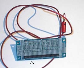
First we make a very simple tool that will simulate all the selection and commands who normally comes from the CPU board. It has a simple signal generator , two extra LED's and the connection cables.
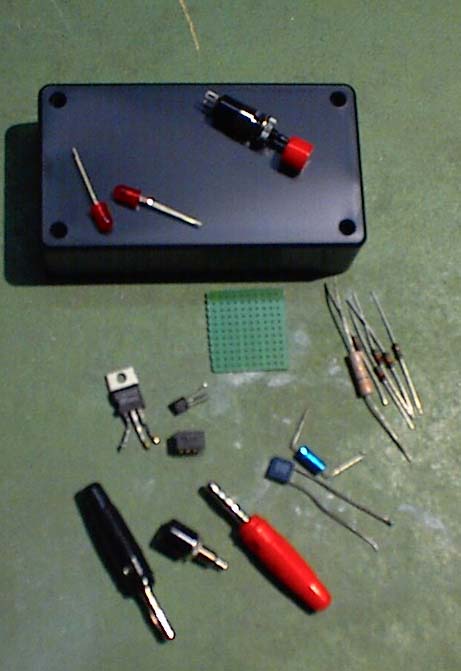
What we need..not very much, adding a neat box to mount everything.
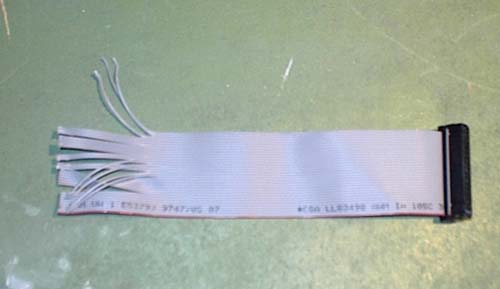
The flat cable fits exactly into J113 ( J102 ) of the driver board, and comes from an old PC , where it was used to connect the floppy drive..
Schematic and connections
Better and complete schematic here ... ![]()
It is a signal generator that gives us a "strong" pulsing signal every 1/2 second that same pulsing will be easy to monitor on the output connectors and during the flow through out the board .
The two LED's , one is a "on" indicator, the second indicate the good working of the generator , and will blink all the time, the connector, 9 leads together going to the signal generator output, and 9 leads going to the push button. Can it be more simple?
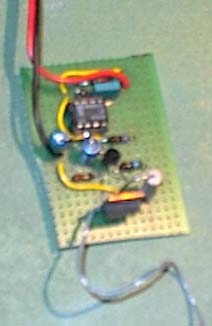
The little signal generator, red lead to the 5 volts , black is ground, gray lead is output
![]()
Mount the little signal generator as on the schematic and we put everything in a handsome box , ready to use with leads to connect to a 5 volt supply, and two extra connection plugs and a push button, leads toward the power driver board to feed it ( 5 volts) and a flat cable , to J113 ( J102 ) of the driver board. The flat cable is the same as used in a PC to connect the Floppy drive , easy to find...
The finished box.
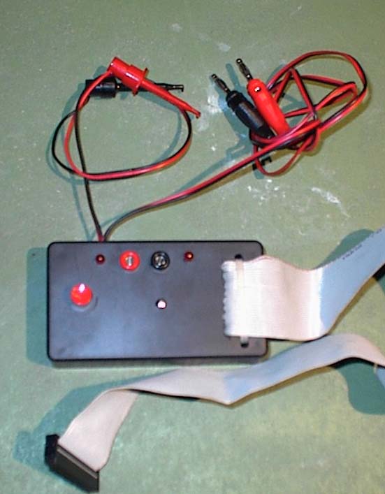
Banana plugs to feed the box ( 5 volts) two leads with grips to connect to the test points +5 and ground of the driver board , feeding the board that way, and the flat cable going to J113 ( J102 ) . The two female banana connector plugs is again the 5 volts , this 5 volt output will be useful during test phase.
![]()
Users manual.
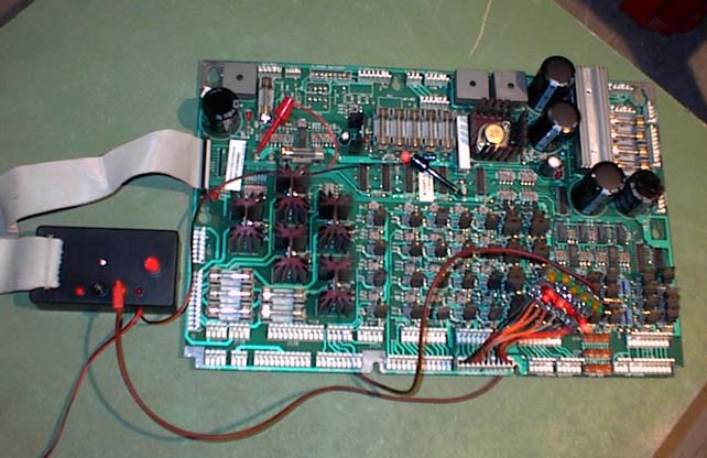
Connect the box to the driver board ,flatcable to J113 ( J102 ), hook up the 5 volts output ( clips) at test point +5 and ground.
Connect the banana plugs into a 5 volt DC supply.
The connected driver board
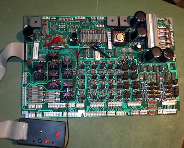
Here you see the connections, at the left the +5 volt test point where the red clip is fixed, and more in the middle the ground test point where the black clip is connected. And of course the flat cable at J113.
![]()
The control leds.
As already used in several repair method for driver boards ( Williams, Bally Atari Zaccaria etc..) we use ,to control the outputs again a row of control leds .. Find here how these are made as already published on this site at several places..
Schematic.
Material used.
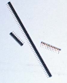
This type of connector strip is soldered at the underside of the little board
Here you can see the connector strip soldered at the back side, this fine connector strip fits into the " Lamp columns" connector that has these fine pins..
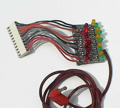
On the front side I soldered the other type of connector ( using short leads) this connector type fits into the bigger connectors at the driver board.This way the test-led- strip can be used on both connector types.The bigger connector is soldered at pin 1, pin3, pin 5 and so on ( impair numbers) and also the impair numbers are red leds the pair numbers are yellow/green leds . All this is helpful when to count and see later which pin of the connector gives us a led that blinks, "stays on" or stays off.
![]()
Mounted with the test leds at connector J 127
Here you see that the +5 volt plug on the box is handy to connect the led strip..
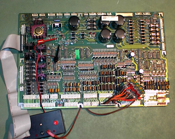
A WPC-95 board , the LED strip is connected at J116.
![]()
Handling
There are three different types of power driver boards , type numbers are, A12697-1, A12697-3, A12697-4 and a driver board for the WPC 95 games, 20028.. The greatest difference between the three boards is that some WPC driver boards have no " flipper enable relay" . This relay situated at the left top of the board will be missing if you have a machine with a" fliptronic" board that commands the flippers.
The test is valuable for all three WPC driver boards. The WPC-95 driver board technology almost the same, has as stated before other connector numbering and smaller fuses. If you want to know which pinball machine has which driver board, look at marvin3m.com under "Williams WPC repair guide" where all the WPC/ WPC-95 pinball machines and there different boards configurations are listed..
We are going to control all outputs of the driver board these are at connectors; J 130, J 127, J 126,J 122, J 121,J 120,J 138and J 135. ( J126,J123,J120,J116,J113,J112,J110,J109 and J106 ) At power up the flipper relay if present will click al the time...Output LED on the control box has to blink all the time.Sometimes the control LED's at any connector will not start to blink, or the flipper relay will not click.. For that, there is the push button on the control box, push him once or twice if needed so that the blinking starts or the relay start to click.( I have no reset coming from the cpu thats why we sometimes ( not often) have to start up with the push button..
Find here the schematic of the power
drive board ...... ![]()
Schematics for WPC-95
board ........... ![]()
![]()
Connect the test LED strip at the connector indicated in red. If outputs are missing always use a logic probe to follow the missing signals as described further.
J130
Some of the outputs going also to J 132 and J131.But we can monitor all signals of this group at J 130. This group is named " High current solenoids " The control LED strip connected at this output pins has to show 8 blinking LED's.If there are some missing or staying lit, we follow the signals starting at U5 , from there to the pré-drivers, Q71,74,72,73,61,60,62 and 59 From there to the drivers, Q81,79,77,76,63,65,67 and 69, and at last to the power output transistors Q82,80,78,76,64,66,68 and 70,. Follow the missing signal , using the schematic and look where it still enters a transistor and fails to come out , easy enough. Replace the suspected element.
J116
Some of the outputs going also to J 116 and J117.But we can monitor all signals of this group at J 116. This group is named " High current drivers " The control LED strip connected at this output pins has to show 8 blinking LED's. If there are some missing or staying lit, we follow the signals starting at U7 , from there to the pré-drivers, Q49 to Q56. From there to the drivers, Q61,57,62,58,63,59,64 and 60, and at last to the power output transistors Q65,69,66,70,67,71,68 and 72,. Follow the missing signal , using the schematic and look where it still enters a transistor and fales to come out , easy enough. Replace the suspected element.
J127
Again some of the outputs are going to other connectors ( J128, 129) but all 8 signals can be monitored at this J127.This group is named" Low current solenoids" .The start is at U4 and the drivers are Q57,55,53,51,49,47,45 and 43. The power out transistors are Q44,46,48,50,52,54,56,and 58. Here to when a output is missing follow the signals using the schematic, really no problem.
J113
Again some of the outputs are going to other connectors ( J114, 115) but all 8 signals can be monitored at this J113.This group is named" Low current drivers". The start is at U6 and the drivers are Q33 to Q40. The power out transistors are Q45,41,46,42,47,43,48,and 44. Here the same scenario, when an output is missing follow the signal from his start at U6 until it disappears there the fault is situated, this using the schematic, really no problem.
J122
These are the " General purpose drivers" and the same signals are also coming to J123 and J124. We monitor at J122 there are only four LED's that must blink here. At pins 1, 2,3 and 4 . The signals start at U2, to the drivers Q19,21,23 and 25 and then to the power drivers Q20,22,24 and 26 .Again a very straight forward circuitry , easy to follow if there is one missing. Mostly it will be the power outputs ( TIP102) that will go bad..
J110
A group called " Device control" using the LED test strip at J110, we must find 4 blinking LED's . On pins 1,2,3 and 4. The signal starts at U4 and passes twice a "gate" . All gates are in IC U3. Really 'straight forward' signals and if one is missing , the only possible cause can be a faulty U3.
J126
Eight more " General purpose drivers" some of them also going to J123. Here the signals start from U 3 to the 8 drivers, Q31,33,29,27,35,37,39 and 41 the output transistors ,again Tip102 are , Q32,34,30,28,36,38,40 and 42.
J109
A first group of " General purpose drivers" , we find the same signals at J108 and J107, with the test LED strip at J109 we have 4 blinking LED's at pins 1,2,3 and 4. The signals are starting at U4, to the drivers Q9,10,11 and 12, en from there towards the power drivers, Q13, 14,15 and 16. A straight forward design , easy to follow, and if one is missing suspect always the output transistor TIP 102...
J112
More " general purpose drivers" 8 of them. You find these signals also at J111. Here the signals starts at U5 to the 8 drivers , Q17 to Q24 and from there to the output transistors, Q29,25,30,26,31,27,32 and 28.
J121
Here we have the " General illumination" outputs, something special, these outputs are coming true TRIAC's and to control these we put of course the LED strip at J121, but we have to ground also pins 12, 11,10,8 and 7 of connector J115 . The outputs will blink 5 LED's. In many cases some LED's stay "on" all the time , even when you have a board that is "good" in the pinball machine.. How comes ? Well the TRIAC is bad but stay's "on" ( conducting) all the time resulting in the general illumination to be on all the time at max strength, not possible to "dim" but as we not always " dim" the illumination this can be not noticed by the user..So be aware the control LED's have to blink!! In almost all cases it is the TRIAC that is bad.. If not look at the drivers they are Q17,9,13,15 and 11. The TRIAC's are at Q18,10,14,16 and 12.On the 5 big heat sinks.
J106
Here we have the " General illumination" outputs, something special, these outputs are coming true TRIAC's and to control these we put of course the LED strip at J106, but we have to ground also pins 10,8 and 7 of connector J103 . The outputs will blink 3 LED's. In many cases some LED's stay "on" all the time , even when you have a board that is "good" in the pinball machine.. How comes ? Well the TRIAC is bad but stay's "on" ( conducting) all the time resulting in the general illumination to be on all the time at max strenght, not possible to "dim" but as we not always " dim" the illumination this can be not noticed by the user..So be aware the control LED's have to blink!! In almost all cases it is the TRIAC that is bad.. If not look at the drivers they are Q6,7 and 8. The TRIAC's are at Q13,4 and 5.On the 3 big heat sinks. You can test also the "unswitched" outputs , the LED strip stay at J106 now ground pins 11 and 12 of J103, again two other LED's will light and will stay " on" all the time. You are controlling the diodes D25,26,29 and 30.
J 138
The " lamp columns" are a bit more tricky . We have , if ok, 8 outputs but the LED strip cannot be used.. The lamp columns work with 18 volts and we do not have that .. So we make a connection between the + 5 volts and the 18 volt test pins on the board. And using a voltmeter, we have to measure each of the 8 pins to see the needle" dance" .Why we cannot use the LED strip instead , well polarity is reversed here and the LED's won't work. But using the voltmeter for just these 8 pins is not to bad.. Again if one missing follow the signals starting at U9 then through U18 driving the chip U19 and then the output transistors Q 91 to Q98..
J123
The " lamp columns" are a bit more tricky . We have , if ok, 8 outputs but the LED strip cannot be used.. The lamp columns work with 18 volts and we do not have that .. So we make a connection between the + 5 volts and the 18 volt test pins on the board. And using a voltmeter, we have to measure each of the 8 pins to see the needle" dance" .Why we cannot use the LED strip instead , well polarity is reversed here and the LED's won't work. But using the voltmeter for just these 8 pins is not to bad.. Again if one missing follow the signals starting at U10 then through U11 driving then the output transistors Q93 to Q100..
J135
The lamp "rows" depending of the initial position of the flip-flops U10, 11 and 12 The 8 LED's will be "on" or "off" , push the button on the control box to change the position of the flip flops , if 8 LED's "on" all is ok. If one or more missing , as always follow the way..here starting at U10, 11 or 12 to the drivers ( TIP 102) Q83 to Q90
J126
The lamp "rows" depending of the initial position of the flip-flops U12, 13, U14 and U15, the 8 LED's will be "on" or "off" , push the button on the control box to change the position of the flip flops , if 8 LED's "on" all is ok. If one or more missing , as always follow the way..here starting at the output pins of the flip-flop's Pin 6 and 8 , and from there directly to the ( TIP102) drivers Q101 to Q108.
WPC
If ever you have a "enable flippers" relay that never clicks , replace Q99. Of course other outputs have been tested and ok at that moment.
WPC-95
J120
A group named "Flippers" here we have again 8 working outputs , but all 12 pins of the connector will blink the connected LED's. Some of the outputs are at two pins at the same time. Pin 2=3, pin 5=6, pin 8=9, pin 12=13. The signals are starting at U8 , passing the drivers Q73 to Q80, going to the output transistors, ( TIP102) Q81,83,86,84,89,87,92 nd 91.
This terminates test of all controls of the driver board . If ever you still have lamps , or solenoids that do not work, well good hunting because you will have to dive under the playfield now, or you have bad contacts in your connectors....
Back to home page ...... ![]()