Pictures of Zaccaria memory signals.
![]()
Here are some oscilloscope pictures of the signals you find on the memory chips when turning round on the memory test.
You can provoque a "bad" memory test when you lift a data pin of the memory..and you will of course also turn round and round on the memory test when you have a bad memory chip..
All the signals ar made at a scoop frequens of 20µsec per division...
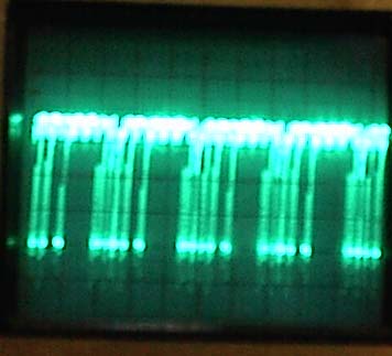
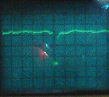
The selection pins 1 to 7 are various signals not a lot to learn here.. i show here pin 1 , 7 ,16 and 17 as examples.
![]()
Selection signals..
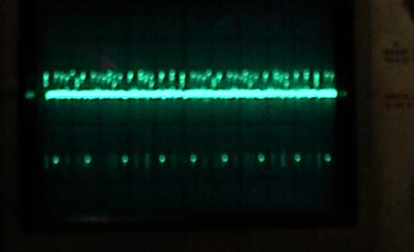
Pin 1
Pin 7 a lot more impulses than 1
Pin 16 very few impulses here, the reason why we cannot measure anything using a universal volt meter..
Pin 17
![]()
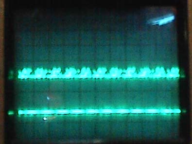
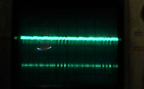
Data signals
One of the data pins (11/12/13/14) they are all the same The goups of pulses you see ( 5 groups here) are the AA's and the 55's written into and read-out from the memory..
![]()
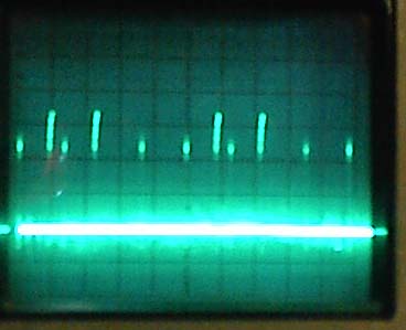
Select and R/W signals
Select signal at pin 8
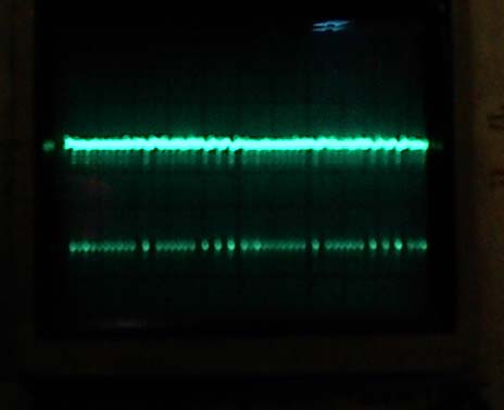
R/W at pin 10
![]()
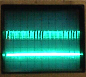
Furthermore i took a picture of pin 8 (select) and pin 10 Read /Write at a scoop frequens of 2µsec per division You see clearly that there are two select impulses for 1 R/W pulse . One selection is during Write ( low = 1 pulse at R/W) and one during Read( high = no pulse at R/W )
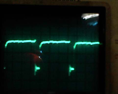
two times "select"
Only one pulse on R/W . Using the same scoop settings as above.
The pulse is during Write
back to Zaccaria cpu page ....... ![]()