Use any Williams 3/4 or type 6 board for any pinball from this series.
![]()
Introduction: I'd like to thank D.Fruleux from France. I used his notes about this subject as the basics for this article. Of course I tested everything myself with success, like using a type 3 cpu board in a Firepower, which usually only works with a type 6 board.....
Sometimes you find a Williams cpu type 3 board or you buy one cheap, but you really need a board type 6 , so bad luck ! Well this can be solved, there is a way to use any board in any Williams pinball of this serie ( type 3 or 4 or 6 ). What you have to do is convert the game eproms, which are usually in three different ICs: IC20, IC17 and IC14. Put them together into a larger eprom type 2764, and then make some changes so that selections still go to the right addresses, no harm will be done at the originallity of the board....
![]()
Start:
In a 2764 we write using an eprom programmer the image of the "game rom " (= IC14 ) starting at adres 0000
The image of IC 17 has to start from 1800
The image of IC 20 starts from 1000. The 2764 is now ready to use.
When i mention IC14 this means IC14 as he can be found NOW on the Williams site . When the pinballs came out of the factory they had more rom chips on the cpu board. There was Ic 21,22 and 26 but as these became obsolete Williams did put all tree together in what they called IC14 .ONE exception was Firpower this pinball had already an IC14 on his CPU board when it came out, therefore the chip that rassembled all the information was called COMBO chip... See the diagram below how everything is stocked into the 2764
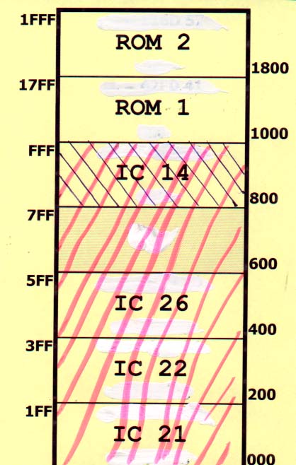
Black arched IC14 represent the "old" IC14 as it was in Firepower . The RED arching is the COMBO chip as you will find now on the Williams site, and hold all the contens of the old obsolete chips IC21,22,26 and IC14.. The "game rom" as you find it now for all other pinballs on the Williams site is always the contens of IC21, IC22 and IC26 all together..Anyway the "game rom or the Combo is always written in the 2764 starting from address 0000( the beginning)
Because the rom contens has been written without any changes into the 2764, there is no problem with copyrights whatsoever.
![]()
Remarque:
As you probably already know, you can
find all the rom images on the official website of Williams... ![]()
The IC14 is always called "Game Rom ". IC 20 usuallyWhite or Green 1, and IC17 usually White of Green 2... For Firepower IC 14 is called Combo rom ...
![]()
Changes:
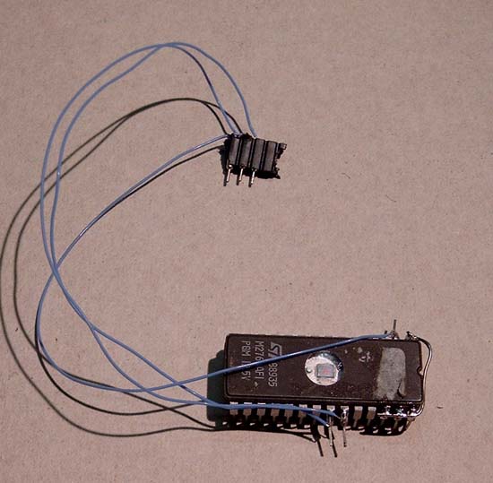
Bend pins 2, 22 and 23 of the 2764 up, so they don't touch the socket.
Place the 2716 in one of the sockets, it doesn't matter which: IC20, IC17 or IC14. BUT put it so that pin 14 gets into pin 12 of the socket !!!! (Do not use socket 14 if your Firepower board already has a combo rom at that place, because the wiring to socket IC14 has been changed already , so use socket 17 in such case. As i said firepower is the only exception)
Pin 1, 28, 27 and 26 should be connected together by soldering a wire on top of the pins.
Remove IC15 from the PCB board.
Connect pin 2 of the 2764 with a wire to hole 13 of socket IC15
Connect pin 22 of the 2764 with a wire to hole 12 of socket IC15
Conenct pin 23 of the 2764 with a wire to hole 14 of socket IC15
In this example I used a small connector with three pins which I'll put into the socket of IC15. I had a socket on IC15, usually this IC is soldered. You do not really have to put a socket, but it's easy in the "try it out phase" that way you can always use your board again as a regular type 3 board by plugging all normal chips back in..
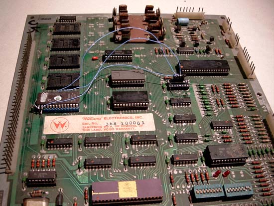
Here you see the 2764 plugged in and the connection to IC15 (with connector)
Again the assembly..
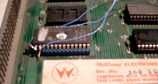
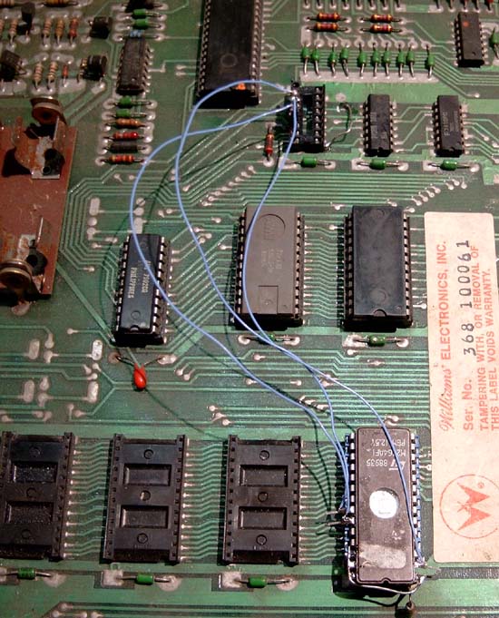
Detailed shot, here you see the longer 2764 sticking over the socket of IC14 , pin 1 connected to 28, 27 and 26; and on pin 2 the blue wire going to IC15...
That's all folks!!
![]()
Type 6 board
Changes when using a type 6 board..
The only difference is that pin 2,22 and 23 have to be connected to holes 3, 1 nd 2 of IC15, which also has to be removed.
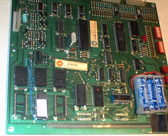
The 2764 on this type 6 board is located in socket IC17 and the tree wires parting in a small hole, left and near IC15, on wich the tree wires are soldered at pins 1,2 and 3 as stated in the text. You see the empty IC15 socket.
![]()
Extra
Interesting: one 2764chip costs only half of the three required 2716 ICs...some cheap eprom burners can't handle the 2716, When refurbushing a cpu board less ROM sockets have to be renewed we only use one....
Back to home page ..![]()