Index Table - Dividing Head
Assembling - Adjustments
Click to enlarge pictures.
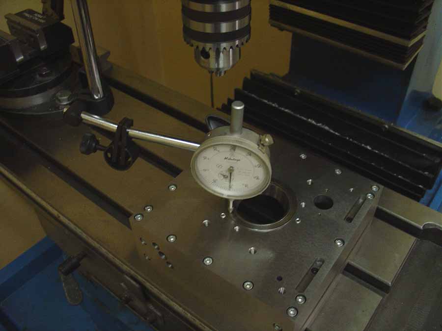
When assembling the chassis
it is important the 5 plates have a perfect right angles to each other. It is recommended to
assemble the chassis upside down on the milling table. after assembling mill the
bottom flat so you're sure the top and bottom are perfectly parallel.
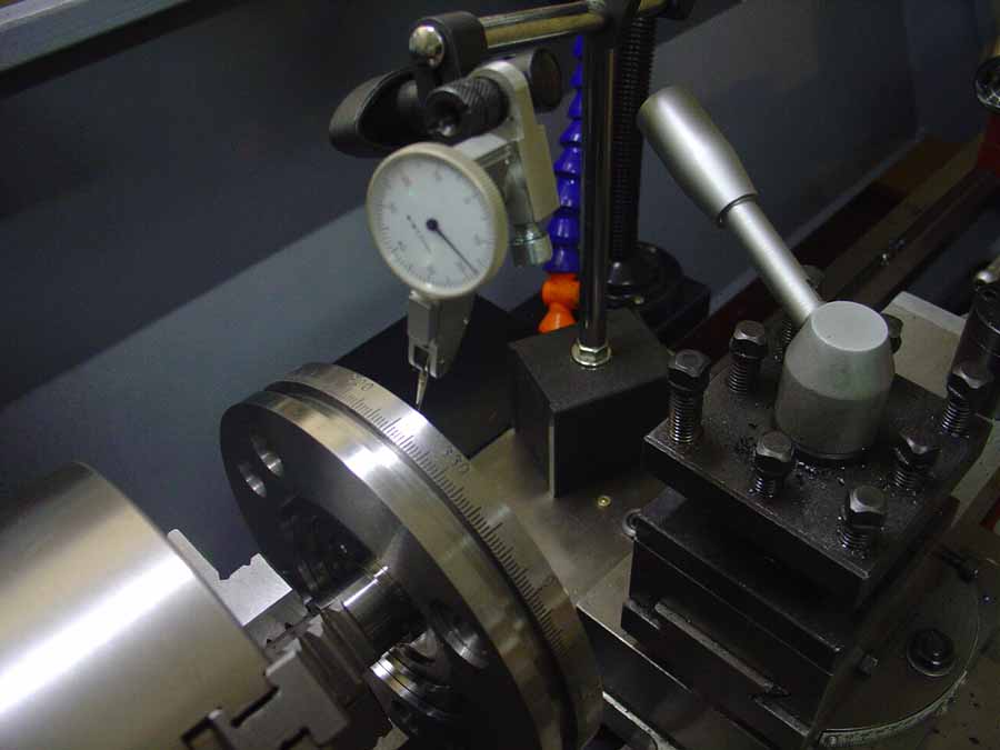
Assemble the table on the main shaft.
You can do this best on the lathe. Clamp the main shaft in the chuck. Check with a dial
indicator the shaft is running perfectly centric. Screw the table on the main shaft. Check with a dial indicator
the table is turning perfectly flat. Through the three mounting bolts tightening or loosening something you can fine-tune it.
Now install the upper bearing carrier in the chassis using three M5 bolts. These bolts are not tightened.
Put the main shaft and table in the bearing. Mount also the two table clamps. Loosen the three bolts down as deep, so the table does not touch the chassis. You can possibly
put some strips of aluminum foil between the table and chassis parts. Set the bearings
tightened with three M5 bolts. The bearing must be completely leveled. Check with a dial indicator and correct the position of the bearing. This procedure, you will have to repeat a few times, to
get the right lower place.
Assemble preliminary the bearing block for the eccentric shaft. Install the lower bearing holder on the lower brackets with 4 bolts M3x10. Slide the worm wheel, with the flange up, on the main shaft and the lower bearing mount bracket with 4 bolts M6. Tighten all on the table
with the clamp bolt, so the table can rotate freely. Lock the clamp bolt with a
M6x10 headles lock bolt. Make sure the table is turning flat and does not rub against the chassis.
The hard part is behind us now.
The metal for the eccentric shaft can locked
now. Assemble now the adjusting metal for the worm shaft and the set screw at the back plate.
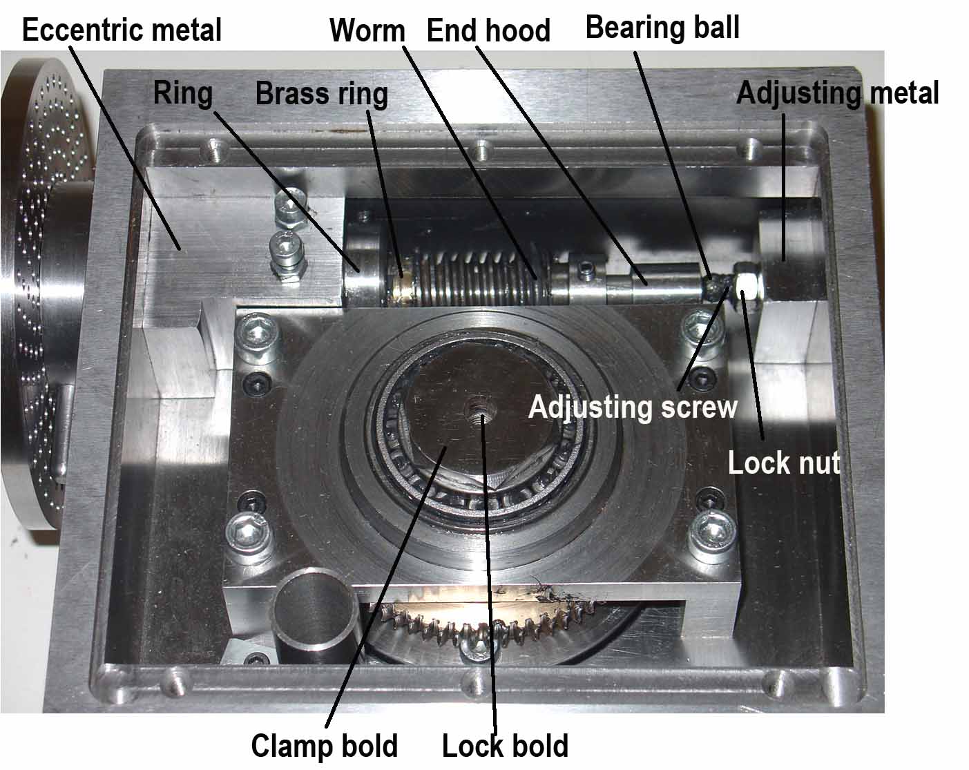
Insert the eccentric shaft in the eccentric metal and tighten the ring and a M4
bolt (See fig. 18). Allow a 0.1 to 0.15 mm gap between the eccentric shaft and the front of the
indextable. Place the worm shaft in the eccentric shaft, slide the brass ring on the shaft and the worm and
the end hood.
Install the handwheel on the worm shaft. Push the brass ring and the worm against the lock ring of the eccentric shaft mounting screws and tighten down the worm. Make sure that
there is a gap of 0.1 to 0.5 mm between the hand wheel and the eccentric
shaft.
Put a bearing ball between the worm shaft adjusting screw and the end hood. Adjust the screw so that the
worm shaft can rotate smoothly and play free. Place the worm on the same level as the worm. Turn the eccentric shaft so that the worm and worm wheel to fit properly. Possibly
adjustment the height of the worm a little. The worm gear can now be tightened to the main
shaft. The left screw on the eccentric metal is adjusted so that the worm
fits smoothly in the worm gear. If there is play between the worm and worm
gear, the adjusting screw must be turned a little bit looser. The adjusting screw is then put down with the locking nut. The other adjustment
screw is the stop adjusting screw for the clearance of the worm. This setting is not really important. I have it set so that the eccentric shaft 90 degrees can be reversed.
Referring now to the handwheel rotates the table about the entire perimeter play smoothly and turn freely.
If at some places during rotation resistance is greater or less, or if in some places
there is a space between the worm and worm wheel, and other places there is not,
then there something wrong with the worm wheel. The worm then runs slightly
out off center. This can easily be solved. Replace the worm by the worm cutter
tool and turn the table around a few times. make sure there is sufficient
pressure between the cutter and the worm wheel. Small errors are then scraped off by the cutter. Replace the worm cutter
tool back through the worm and everything will run perfectly.