Index Table - Dividing Head
Small parts and Hand wheel
Click to enlarge pictures.
Making the small parts of drawing p. 11 and p. 18 required, except on the
two table clamps and the worm shaft adjusting bolt, no further explanation.
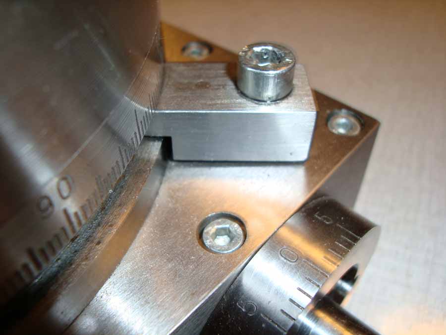
The table clamps are milled as shown. The pin is attached to the
clamp. This may be a bit of glue or make the pin a little longer and flat with a
hammer to beat, after which the whole surface is sanded. The two springs
around the pins to press the clamps upwards, I have made from a ball pen spring.
The adjusting bolt of the worm shaft is an M6x30 Allen bolt.
The end of the bolt is in the lathe centred with a centre drill and drilled a little bit
with an 8 mm drill so the bearing ball stay in place.

The hand wheel should fit the worm shaft. The worm shaft has a flat side of 9.5mm.
To make the hand wheel with a hole of 15 mm and a flat end, you need a special machine.
With a milling machine is hard to achieve.
Therefore the hand wheel is made in two parts as shown on drawing page 12.
In the part with the scale ring is a 9 mm hole drilled.
This hole is cutted out on the lathe to a diameter of 15 mm over a length of 19 mm.
At the other end the hole is rectangular milled so the flat
end of the worm shaft fits. The two parts are screwed together with two bolts of
M3x25 bolts.
The other parts of the hand wheel ask no further explanation and are made as shown on the drawings.
Now already make the mounting clamps. You can clamp the index table on the milling table during assembling.