Index Table - Dividing Head
Chassis and Table
Click to enlarge pictures.
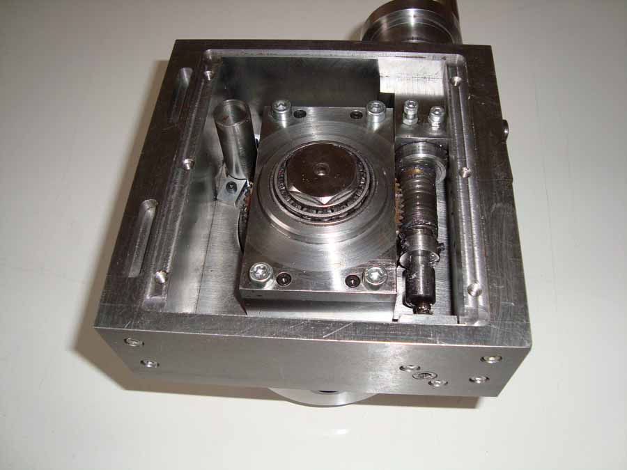
The main chassis is made up of 5 steel plates. (Drawings page 1 to page 4) .The top
plate is a few millimeters larger than the final size and is turned down on the
lathe to obtain a flat surface. Drill a hole in the centre of the plate and enlarge the hole for the
upper bearing holder. Mill the sides to final size making sure the bearing
holder remains in the center of the plate. Drill all the holes as indicated on
drawing Page 1. Complete the other chassis plates as per drawings no further
explanation is necessary.
It is most important that all side plates be
perpendicular to the top chassis plate .It is recommended to mount the chassis
upside down on the milling table and mill the bottom perfectly flat, making
sure top and bottom are perfectly parallel.
The table runs on two taper bearings. The upper bearing has a shaft diameter of 25mm, the bearing holder is adjustable. The lower bearing holder has a shaft diameter of 20mm and is fixed. The central shaft is made in one operation so the eccentricity is limited to a minimum. Turn the first section of 20mm then the 25mm and finally the 30mm. Now set the tool post slide at 3 degrees and cut the upper taper. Drill a hole of 9mm in the shaft and tap a thread of M10 x 1. If everything is ready the part can be turned in the chuck. Leave the tool post slide on 3 degrees and make sure the tapered part in the table matches exactly the same angle as the shaft head.
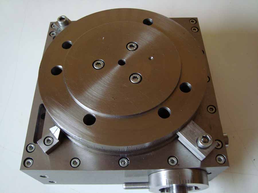
To make the table you start by cutting the outside diameter to the precise dimensions. Then cut the front surface. Turn the slot for the clamps. Cut the hole at an angle of 3 degrees. As you have left the tool post on 3 degrees this is not a problem. Cut the internal diameter so that the shaft head goes fully into the hole but the backside must be free. The table should now be reversed in the chuck. Check with a dial indicator that the table is clamped right in the chuck. Also check roundness accuracy. I have chucked the table in the independent four-jaw chuck and after assembling I have a roundness accuracy of 0.01mm. Now the other side can be cut. The collar should be exactly 95mm so a 120mm chuck can be mounted without slack.
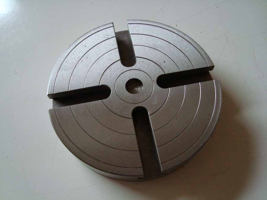
To make the chuck plate you start to cut the plate with a correct diameter and then cut the front surface. Cut the collar hole to 95 mm. It must fit on the table collar. The plates should now be reversed in the chuck. Check with a dial indicator that the table is clamped right in the chuck. Also check the roundness accuracy. Now chuck the table in the independent four-jaw chuck and cut the other side. With a point cutting tool, the 5 concentric circles are cut. In the center cut a 14mm diameter hole, 4mm deep. You can use it later to center your work with a center shaft.

Making the upper bearing holder is normally not a problem. The opening of the bearing is 0.01 to 0.02 mm smaller than the outer diameter of the bearing. The bearing can so easily be pressed into the bearing holder. If you, like me, not have a press it easily to do it on the lathe. Place the bearing holder flat against the lathe chuck. Place the bearing in front of the bearing hole. With the tailstock you can press the bearing in the bearing holder. Do not forget to oil the bearing whole end the bearing outside.
The lower bearing holder I have made on the lathe. The work piece was chucked in the independent four-jaw chuck. The rectangular surface of the bearing holder and the supports are finished on the milling machine.
This picture is only an example.
Because it is difficult to drill the holes in the main shaft, table and chuck plate on the right centers without a turntable, you can use the coordinate drilling diagram. With this drawing you can easily drill the holes on the milling machine at exactly the right place.
The clamping bolt is made of a M20 coarse bolt.